I check the model by hand before I trust it.
BE Civil, IOE Pashchimanchal (TU), 2025 · NEC Registered Engineer Hand calculations are published beside every model so the work can be checked.
Register
Five items. Three self-directed studies since graduating, one final-year laboratory project, one internship. Nothing here is client work.
| No. | Title | Type | Tools | Codes | Status | Year |
|---|---|---|---|---|---|---|
| 02-A | 3-storey RC frame, LalitpurBase shear by hand to NBC 105:2025, checked against ETABS | Structural | ETABS · QGIS | NBC 105:2025 · IS 456 | Independent study | 2026 |
| 02-B | Masonry infill as an equivalent diagonal strutShort-column shear demand and the confinement IS 13920 requires | Structural | ETABS | FEMA 356 / ASCE 41 · IS 13920:2016 | Independent study | 2026 |
| 02-C | G+5 frame on a spring-supported raft, Madhyapur ThimiSoil–structure interaction, moment redistribution, settlement compatibility | Geotechnical | ETABS · SAFE · QGIS | NBC 105:2025 · IS 1904 · IS 456 | Independent study | 2026 |
| 03 | Siddhababa tunnel spoil as road aggregate127 kg sample, AIV / ACV / LAA / CBR / cube strength | Materials | Lab · Excel | IS 2386 · IS 2720 · IS 516 · MoRTH | Major project | 2025 |
| 04 | Naksawala Engineering Solution, ButwalNaksha Pass drawing sets, BOQ and rate analysis, SketchUp models | Drafting · Estimation | AutoCAD · Excel · SketchUp | Municipal bylaws | Internship | 2025 |
A 3-storey RC frame in Lalitpur, base shear by hand.
A small office frame, sized so the whole equivalent-static calculation fits on one sheet. The point of the exercise is the hand check: every input traced to a clause, then the ETABS model has to agree with it.
Problem
Three-storey reinforced-concrete moment-resisting frame, office use (under 500 persons), on a Lalitpur site inside the Kathmandu Valley. Plan 2 × 2 bays at 3.66 m (12 ft), storey height 3.05 m, H = 9.15 m to roof. What is the design base shear under NBC 105:2025, and what drift limits does the model have to meet?
Site: Jawalakhel, Lalitpur Metropolitan City ward 3/4 (Table 4-3 lists wards 1–4, 6–13, 16, 17, 19, 20 as Soil Type D by default).
Method
Equivalent Static Method, NBC 105:2025 Section 6. Lalitpur Metropolitan City ward 3/4 is listed in Table 4-3, so Soil Type D by default (cl. 4.1.3.3) unless a 30 m profile shows otherwise; I keep the default. Seismic weight uses the code’s live-load factors, not the IS 1893 ones. ETABS model: 3-D frame, rigid diaphragms, cracked-section stiffness per cl. 3.4, user-defined Type D spectrum.
Hand check
| Item | Value | Ref. | |
|---|---|---|---|
| Period | |||
| 1 | Empirical period, RC moment frame, kt = 0.075 T1 = kt · H0.75 = 0.075 × 9.150.75 = 0.075 × 5.26 | 0.39 s | cl. 5.1.2, eq. 5.1(2) |
| 2 | Amplify approximate period by 1.25 for design T1 = 1.25 × 0.39 | 0.49 s | cl. 5.1.3 |
| Elastic site spectrum | |||
| 3 | Site: Lalitpur Metropolitan City ward 3/4, listed in Table 4-3 → Soil Type D by default. Plateau α = 2.25, flat from Ta = 0 to Tc = 2.0 s (Equivalent Static Method) T1 = 0.49 s < Tc → Ch(T1) = α | 2.25 | cl. 4.1.3.3; Table 4-1, 4-3 |
| 4 | Seismic zoning factor, Lalitpur | Z = 0.35 | cl. 4.1.4, Annex C |
| 5 | Importance factor, Class I (office, < 500 persons) | I = 1.0 | cl. 4.1.5, Table 4-4 |
| 6 | Elastic site spectrum C(T1) = Ch(T1) · Z · I = 2.25 × 0.35 × 1.0 | 0.788 | cl. 4.1.1, eq. 4.1(1) |
| Design coefficient, ultimate limit state | |||
| 7 | Ductility and overstrength, RC moment-resisting frame | Rμ = 4 · Ωu = 1.5 | cl. 5.3.2, 5.3.3, Table 5-2 |
| 8 | Horizontal base shear coefficient Cd(T1) = C(T1) / (Rμ · Ωu) = 0.788 / (4 × 1.5) | 0.131 | cl. 6.1.1, eq. 6.1(1) |
| Seismic weight and base shear | |||
| 9 | Seismic weight, W = DL + λ·LL with λ = 0.30 for offices, roof live load nil Taken as ≈ 600 kN per level over the 7.3 m × 7.3 m plan, ≈ 11 kN/m² including partitions and 0.3 LL | W = 1800 kN | cl. 5.2, Table 5-1 |
| 10 | Design base shear V = Cd(T1) · W = 0.131 × 1800 | V ≈ 236 kN | cl. 6.2, eq. 6.2(1) |
| Serviceability limit state | |||
| 11 | Serviceability spectrum and coefficient, Ωs = 1.25 Cs(T1) = 0.20 · C(T1) = 0.158; Cd,s = Cs / Ωs = 0.126 | Vs ≈ 227 kN | cl. 4.2, eq. 4.2(1); cl. 6.1.2 |
| Drift limits for the model | |||
| 12 | Inter-storey drift ratio. ULS: elastic drift × Rμ = 4 (cl. 5.5.1.1), ≤ 0.025; SLS: unamplified, ≤ 0.006 (cl. 5.5.3); stiffness per Table 3-1. | ≤ 0.025 ULS · ≤ 0.006 SLS | cl. 5.5.1, 5.5.3; Table 3-1 |
Result
Design base shear ≈ 236 kN on a 1800 kN frame, i.e. 13.1% of seismic weight. On the Type D plateau the coefficient does not change between 0 and 2.0 s, so the period estimate affects drift, not base shear, for a frame this stiff.
ETABS comparison withheld. The model is being re-run with the NBC 105:2025 Soil Type D user spectrum and cracked stiffness. The verification table (T1, V, storey drifts — hand vs model) will be added once those numbers exist; design T = min(0.49 s, Tmodel), cl. 5.1. I am not publishing figures from the earlier run.
Limitations
- Seismic weight is estimated from unit loads, not taken off a finished drawing set; the frame is a study object, not a building.
- Soil Type D is the code default for the ward. A borehole to 30 m could move the site to Type C and change Ch.
- Torsion (accidental eccentricity ±0.05b, cl. 5.6) and vertical distribution of V are in the model and not shown here.
Masonry infill as a diagonal strut, and what it does to the columns.
Nepali frames are almost always filled with 230 mm clay brick and almost always analysed bare. The infill is usually ignored for well-understood, code-sanctioned reasons; this study puts a number on what the bare-frame assumption leaves out, especially column shear next to partial-height walls.
Problem
A bare RC frame model gives the right global stiffness only if the walls are isolated from it. When masonry is built tight against the columns it acts as a compression strut, shortening the period, taking most of the storey shear, and, where the wall stops short of the beam, turning a full-height column into a short one. How large are those effects on a typical frame, and does standard detailing cover them?
Method
Each panel replaced by a single equivalent diagonal strut (Mainstone; FEMA 356 eq. 7-14, carried unchanged into ASCE 41) of width w and thickness t, modelled in ETABS as a compression-only link with axial stiffness Em·w·t / rinf. Two models compared: bare frame, and the same frame with struts in all exterior panels plus a partial-height (sill-level) infill in one bay to produce the short-column condition. Equivalent static loading as on Sheet 02-A.
Hand check
| Item | Value | Ref. | |
|---|---|---|---|
| 1 | Panel 3.0 m × 3.0 m clear, clay brick t = 230 mm, Em = 2 500 MPa; diagonal at θ = 45° | sin 2θ = 1.0 | |
| 2 | Frame M25: Ec = 5000√fck; Ic = 1.87 × 109 mm4 (350 × 400, in-plane); hinf = 3000 mm clear, hcol taken = 3000 mm (centreline height gives w ≈ 460 mm) | Ec = 25 000 MPa | IS 456 cl. 6.2.3.1 |
| 3 | Relative stiffness parameter λ = [Em t sin 2θ / (4 Ec Ic hinf)]¼ = [2500 × 230 × 1.0 / (4 × 25 000 × 1.87×109 × 3000)]¼ | 1.01 × 10⁻³ /mm | FEMA 356 eq. 7-14 |
| 4 | λ · hcol = 1.01×10−3 × 3000 | 3.02 | |
| 5 | Diagonal length of panel rinf = √(3000² + 3000²) | 4 243 mm | |
| 6 | Equivalent strut width w = 0.175 (λ hcol)−0.4 rinf = 0.175 × 0.643 × 4243 = 477 | w ≈ 480 mm | FEMA 356 eq. 7-14 |
| 7 | Strut axial stiffness for the ETABS link, compression only k = Em w t / rinf = 2500 × 480 × 230 / 4243 | ≈ 65 kN/mm | |
| Confinement next to partial infill, 350 × 400 column | |||
| 8 | Special confining reinforcement over the full column height where infill is partial; hoop spacing ≤ min(Bc/4, 8 db, 100 mm) — NBC 105:2025 Annex A cl. 4.3(b); IS 13920:2016 (Amd 1) cl. 7.6.1(b): ≤ 6 db. Bc/4 = 87.5 mm, 6 db = 96 mm (16 mm bars) → adopt 75 mm | Ø10 + ties @ 75 c/c | NBC 105 Annex A cl. 4.3(b) IS 13920 cl. 7.6.1(b) |
| 9 | Ash (h = 160 mm with cross-ties, Fe500 ties, M25) = 67 mm² per leg at s = 75 → Ø10 (78.5 mm²) ok, Ø8 (50.3 mm²) no. | Ø10 ok · Ø8 no | NBC 105 Annex A cl. 4.3(c), eq. 4.3.3; cross-tie per cl. 4.2.3(d) |
Result
- Global
- With struts the period drops and drifts drop. Under equivalent static loading the base shear is unchanged (same plateau coefficient, same W; it rises only if infill self-weight is added to W). What changes is the path: the struts carry most of the storey shear and deliver it into the column ends.
- Short column
- Shear demand on the column beside the sill-level infill is roughly +79% over the bare-frame value in the study frame. That is the number the bare model cannot see.
- Detailing
- IS 13920:2016 cl. 7.6.4 (cl. 8.4 in the unamended print: ‘masonry wall adjoining column and extending only for partial column height’) and NBC 105:2025 Annex A cl. 4.3(e) already mandate full-height special confinement for exactly this case, so the study quantifies why the code asks for it rather than discovering anything: for the 350 × 400 column, Ø10 hoops with cross-ties at 75 mm centres over the full height. Ø8 does not meet the Ash requirement at that spacing (row 9).
- Alternative
- Isolate the wall with a slip joint / movement gap at the columns and beam soffit so it never becomes a strut, and then the bare-frame model is the right one.
- Site QC
- Either way the drawing has to say which. Masonry wedged tight against columns on site produces the strut whether or not it was modelled.
Limitations
- A single concentric strut reproduces global stiffness but not the local contact length or the shear it delivers to the column end; the +79 % is from an off-centre strut arrangement and should be read as an order of magnitude.
- Openings are not modelled. Em = 2 500 MPa is assumed for local clay brick, not tested.
- No pushover or hinge results; the study is linear.
A G+5 frame on a raft, with the soil in the model.
Deep, soft Valley sediments make a fixed base a poor assumption. This study puts Winkler springs under a six-storey commercial frame in Madhyapur Thimi and looks at what moves: periods, column moments, drift, and the raft.
Problem
G+5 RC commercial frame, 24 m × 18 m in plan on a 6 m grid, at Madhyapur Thimi, Bhaktapur. Ground: 40 m+ of soft-to-medium clay and silt over dense sand; allowable bearing pressure qa ≈ 120 kPa; water table at 2.5 m. Question: how do the fixed-base and spring-supported models differ, and does a 600 mm raft work under the redistributed loads?
Method
Two ETABS models under the same NBC 105:2025 loading (Bhaktapur, Z = 0.35, Soil Type D): fixed supports, and vertical springs Kz = ks × Atrib at each column base, with ks from an SPT correlation. Column reactions from the spring model exported to SAFE for the raft: 600 mm thick, M30, punching shear and flexure, and settlement. Liquefaction susceptibility of the site read from the published Kathmandu Valley liquefaction hazard mapping (JICA 2002 study), overlaid on the site in QGIS.
Hand check
| Item | Value | Ref. | |
|---|---|---|---|
| 1 | Vertical spring at an interior column, 6 m × 6 m tributary Kz = ks · Atrib = 15 000 × 36 Kz = ks·Atrib (edge ½, corner ¼ of area); Bowles suggests doubling edge springs for continuity — not done here. ks ≈ 15 000 kN/m³ from SPT is a small-footing value; for an 18 m wide raft on deep clay it is an upper bound (size effect, consolidation). | 5.4 × 10⁵ kN/m | Bowles |
| 2 | Period, fixed base → springs (from the models) 0.82 s → 1.14 s, +39% | both < Tc = 2.0 s | NBC 105 Table 4-1 |
| 3 | Consequence on the Type D plateau: Ch(T) = 2.25 for both, so Cd and V are unchanged by the softer base. SSI here redistributes forces; it does not reduce them. | ΔV = 0 | cl. 4.1.2, cl. 6.1.1 |
| 4 | Differential settlement between adjacent columns (SAFE), δ = 18 mm over L = 6 m δ / L = 18 / 6000 | 1/333 | |
| 5 | Angular distortion limit — IS 1904:1986 Table 1 row iii(a): raft on plastic clay, framed with panel walls — 1/300, differential ≤ 0.0033L = 20 mm > 18 mm | 1/333 < 1/300 | IS 1904:1986 Table 1 iii(a) |
Result
- Period
- T1 = 0.82 s fixed → 1.14 s on springs, +39%; both under Tc = 2.0 s.
- Base shear
- Cd = 0.131 in both models: on the Type D plateau the softer base changes nothing in V. SSI here redistributes forces; it does not reduce them.
- Column moments
- At the base −23%; the moment moves up to mid-height and into the first-floor beams, so a fixed-base design detailed to fixed-base moments is unconservative in those regions.
- Drift
- Maximum inter-storey drift +29%, about a third, which is where the SLS check bites.
- Raft
- 600 mm, M30, verified in SAFE for flexure and punching under the redistributed column loads, IS 456 cl. 34.2.4 (cl. 31.6 procedure).
- Settlement
- Differential 18 mm over the 6 m bay → 1/333, inside the 1/300 of IS 1904:1986 Table 1 row iii(a).
Limitations
- The published hazard mapping puts the site in a high liquefaction-susceptibility band. NBC 105:2025 cl. 2.3.3 says design must account for potential soil movement on such ground and that pile foundations are normally preferred. The raft here is the study's subject, not a recommendation; the next step is a liquefaction assessment and a piled alternative.
- Linear Winkler springs do not capture consolidation settlement or the size effect on ks; a plate-load or consolidation-based modulus would lower the springs.
- 1/333 passes row iii(a) but not the 1/500 of row ii / Skempton–MacDonald cracking limit; on this soil the infill would crack before the frame minds.
Can Siddhababa tunnel spoil be used as road aggregate?
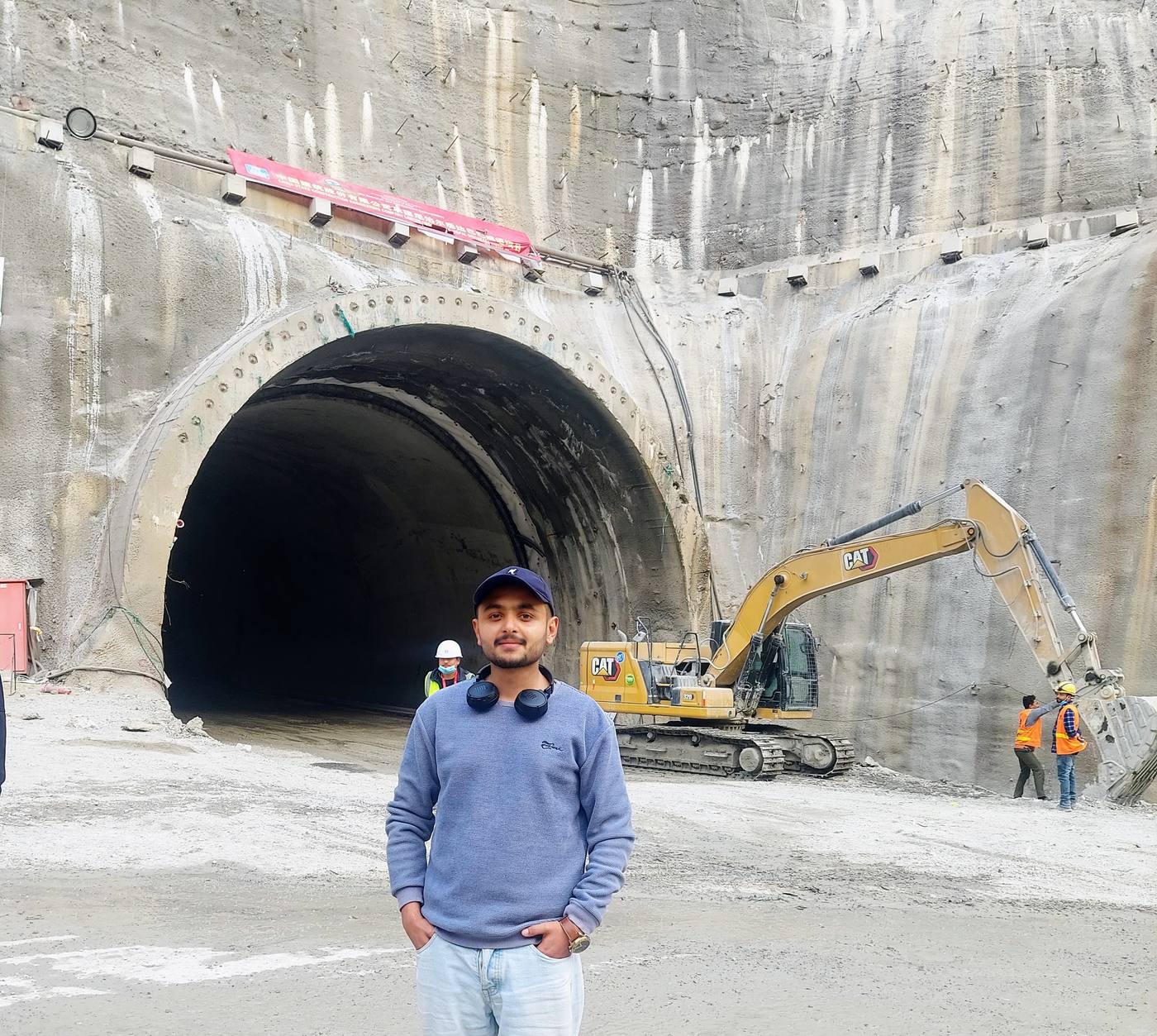
A 127 kg sample of sedimentary rock excavated from the Siddhababa tunnel (Palpa–Rupandehi) was crushed and tested in the campus laboratory against Indian Standards and MoRTH limits. If it passes, the spoil goes into the approach road instead of a tip, and less rock is quarried and hauled in.
Results
| Test | Standard | Result | Limit | Verdict |
|---|---|---|---|---|
| Aggregate Impact Value | IS 2386 Pt IV | 20 % | ≤ 40 % GSB (Table 400-2) · ≤ 30 % WMM (Table 400-11) · ≤ 24 % BC (Table 500-17) | ✓ base & sub-base · ✓ wearing |
| Aggregate Crushing Value | IS 2386 Pt IV | 34.9 % | ≤ 45 % non-wearing · ≤ 30 % wearing surfaces (IS 383) | ✓ base & sub-base · ✗ wearing course |
| Los Angeles Abrasion | IS 2386 Pt IV | 8.5 – 17.3 % | ≤ 40 % WMM (Table 400-11) · ≤ 30 % BC (Table 500-17) | ✓ all layers (see note 1) |
| California Bearing Ratio | IS 2720 Pt 16 | 85 % unsoaked | ≥ 30 % for GSB material, 4-day soaked basis | ✓ provisional · soaked test pending |
| Cube compressive strength, 28 d | IS 516 | 25 MPa | IS 456 Table 11 mean criterion fck + 4: M20 ≥ 24 MPa, M25 ≥ 29 MPa (single trial batch) | ✓ M20 · ✗ M25 as mixed |
- 1. An LAA of 8–17 % is unusually low for sedimentary rock and sits oddly beside an ACV of 35 %; the abrasion test should be repeated on a fresh split before the value is used in a specification.
- 2. Grading (particle-size distribution) was run per IS 2386 Pt I; the blend would need adjustment to a MoRTH grading envelope, which is a mix-design task rather than a material property.
Conclusion
The spoil meets MoRTH limits for granular sub-base (GSB) and wet-mix macadam (WMM) base. It does not qualify for a bituminous wearing course because ACV exceeds 30 %. As coarse aggregate in concrete the trial mix reached 25 MPa at 28 days, adequate for M20; reaching an M25 target strength needs a mix adjustment (lower w/c, or a higher cement content), not a different aggregate.
The practical case is haulage: aggregate that is already at the portal does not need to be quarried in the Siwaliks and trucked up the Siddhartha Highway.
Limitations
- One 127 kg sample from one location in the bore; variability along the tunnel is untested.
- CBR is unsoaked. The specification basis is the 4-day soaked value, which will be lower.
- Water absorption and soundness were not tested.
Profile
Civil engineer (BE, IOE Pashchimanchal 2025; NEC-registered General ‘A’). Six months at Naksawala Engineering, Butwal, producing municipal-approval drawing sets, BOQs and rate analyses. Final-year lab project on reusing Siddhababa tunnel spoil as road aggregate. Since graduating I have been teaching myself seismic design to NBC 105:2025 through three self-directed ETABS/SAFE studies, and I publish the hand calculations alongside the models so the work can be checked. Looking for a junior structural or site role in Nepal where I can work under a licensed designer.
Experience
- Municipal-approval (Naksha Pass) drawing sets in AutoCAD: architectural and structural plans checked against the local building bylaws.
- Bills of quantities, cost estimates and rate analyses in Excel for tender documents and material procurement.
- SketchUp 3-D models of proposed buildings for client review.
Education
Software
- ETABS, SAFE
- AutoCAD 2D / 3D
- SketchUp
- QGIS
- MS Excel BOQ, rate analysis
Laboratory
- Concrete cubes IS 516
- AIV, ACV, LAA IS 2386
- CBR IS 2720
- Particle-size distribution
Codes used
- NBC 105:2025 incl. Annex A, RC detailing
- IS 456:2000 · IS 13920:2016
- IS 2386 · IS 2720 · MoRTH
- FEMA 356 / ASCE 41 equivalent strut
Registration, certificate, languages
- Nepal Engineering Council — Registered Engineer, General ‘A’
- AutoCAD Essentials — SourceCAD
- English · Nepali · Hindi

If the calc sheet reads right to you, write to me.
Set in Newsreader, IBM Plex Sans and IBM Plex Mono. No frameworks, no tracking.